Thursday, May 10, 2007

Revit, Random, and different platforms...


One thing i always "ASSumed" about 3D modeling and Consultant Coordination, was that in some way shape or form, everyone would "see" your model, and could derive object locations based on it. So when i heard that (for some reason), we had to provide actual coordinates for a floor opening that is (somewhat) random in design, i was curious. "Aren't they working with our model overlayed?" "Well yes, but..."

I digress. Its not the point anyway. A couple of people in the office began wondering how an object in Revit would report coordinates relative to a structural grid. Granted, the Spot Dim. tool reports coordinates, but our structural grid was not aligned with the coordinate system (and we couldn't adjust, there was another coord. system, etc...) So anyway...

My solution was a simple one, its been done many times. We use Parameters to Drive geometry, so i thought id just reverse engineer a family, so the geometry could drive the Parameters, giving a dimension. Its NOT a 100% intelligent tool, and its certainly not "user-proof," but i don't believe we'll ever be "User proof" :-)

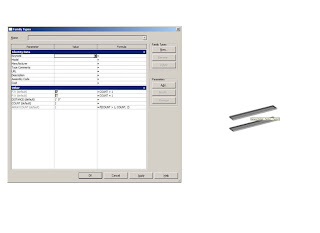
All the family entailed, was two Crosshairs, which i just made from Specialty Equipment Families to be consistent. (The whole assembly is a Spec. Equip. family so it can be scheduled...) In any event, the Distance Parameters have to be shared, obviously... That way they can be reported in a schedule.
Where its UNintelligent, is in the smaller crosshair. Ideally, we could intelligently have it report where it lies, but i dont know of a way to accomplish this. So the accuracy of this tool rests in someone aligning the smaller crosshair to a common "origin" from which to report. With Revit's Multiple Alignment tool, this takes about two seconds. :) The DIMS go to the reference planes, which the Crosshair is locked to. In the project, this gives us pull tabs, which are great for this application.
For ease of use, i prefer to insert them and copy them around so they're already on the "random" points i need coordinates for. You can put them on the "origin" first, and stretch/align them, but then you have a number of points in different locations to deal with. Since they're all connected to the same Critical Origin, i like to get the random points out of the way when i drop them in. Then i can multiple align to the "origin". (I'm using the term in quotes because its not an origin, its just a base point... Just wanted to clarify). the little "legs" hanging out in space are what need to be aligned to a common point. Because of the pull tabs, you can literally just "align" with the Crosshair.


There are the pull tabs, if you choose to go that route... I prefer the align tool for this application, but i can see why it may not be ideal. The align tool is tough if your object isn't parallel with the Crosshair, so i was using a Component that was just an empty crosshair, that i placed on all the Floor Edges ahead of time. Again, not a perfect solution, as it requires of you to accurately pick the points to be located and scheduled.

I think a better solution could be had of those Spot Coordinates... I don't believe we can schedule them, but if we could... Wow, that could go places. Calculated values accounting for the grid orientation shift and/or the "origin" in use... And it would all stay live... BUT, you'd still have to clock the points. So I'm not sure its possible to eliminate us from the game. I guess we all get to keep our jobs today. :) So anyway, i put a bunch of them in, and did the multiple align to the two grids I'm using as my Benchmark.


I have to admit... After a few years at UB doing Ink on Mylar of obscure objects, part of me wanted to print this... for no practical use. But alas, save a tree, hit Print Screen, lol.


Those are all the markers after having the crosshair aligned to the "origin." About ten minutes of work, then i tagged them. That took a while, because we cant specify in the family, WHERE the tag goes in, so it defaults to the center of the family... Which makes me cry in this instance. I had to move the tags, which also is a liability in the fidelity of the model... But, since the coordinates and the schedule will always be right, its a visual mis-cue, if anything.


In the family, i put in a Visibility Parameter for the Connecting Line, so i could shut them off in the end. Here are the markers, with the lines disabled. Pretty simple, really.


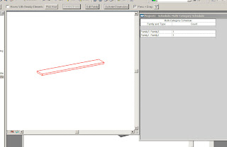
Here's the schedule with the values reported. Some of them are horrible numbers (Rays rule for precision...), but that's what it actually is, right? Id like to play around with something similar in principle, but much bigger in design. Maybe take something like one of the Morphosis Buildings, and try breaking it down.
Gehry Tech.'s Digital Project is great at documenting complex relationships, where structure is based on form, which is based on some mathematical algorithm... But one has to wonder: What happens in a case like this, where someone ELSE'S software, that DOESN'T read the formulas, needs values for location off something like that? I liked this exercise for that reason alone... Its easy to say CAD standards are heading by the way side, and Schedules are live, and information now has to be displayed and conveyed in a fashion that doesn't compromise the integrity of our models... But with ArchiCAD, Revit, DP, RISA3D, Solidworks, and on and on and on... There is obviously a communication breakdown, save for things like IFC (which i know little about at this point). So what do we have to look forward to, in terms of breaking down information in to values everyone can appreciate? Because at the end of the day, I'm betting that a gorgeous 3D model isn't turning in to a building unless the Structural guy knows where to put the Steel. :-)

Tuesday, May 1, 2007

Bentley Architecture?

I haven't gotten a chance to even DL the trial yet, but I'm going to. Its based on Microstation, i suppose, since you must have the latter to try out the former. Ive never used either, but in the spirit of staying Objective about Revit I'm going to Download it this weekend.

Granted, i haven't spent a great deal of time with the various platforms I've used... But I've used a few, and i prefer it that way. So far I've been the happiest and most successful with Revit, for a number of reasons. Yet, having been down other roads always offers perspective, and from it, appreciation for the things we have. :)

Anyone try Bentley Architecture yet?

Additive Information... And the Human Implication.

I'm working on an Egress Plan on Revit, and awhile back i took my best shot at automating it. For this particular job, we are taking the SF, calling 90 percent sales, 10 percent stock, and calculating the number of exits based on number of occupants, based on the SF.

Now, it was fairly simple to do, until i decided i wanted a check in place in case i didn't have the correct number of exits. This wasn't difficult, more than irritating to set up. And in the end, while it works, every person must now know how it works: Exit tags by doors are really Area Tags, that way the value of Door Capacity can be a property of the Area. This lets a string of formulas and calculated values all stem from the area of the "Area", which works nicely.

There is a schedule on our drawing sheet, that only shows up if some of the values are not correct, warning you to go to your automated schedule to check the exits and such. This was a great idea i got from Steve Stafford. (Works great Steve!).

This method hasn't let me down yet, unless.... I simply never define an "Area." Maybe there is a space that was "Area 2c03", but somewhere along the way it got bisected by a demise wall, and the origin for said Area is on one half. Well, if i never place an "Area" entity in the other half, all of the calculations are moot, yes? Depending on what platform you work in (I'm in Revit obviously, but that isn't the point of this post) there may be options, depending on how different platforms work. Ours treats Areas and Rooms as objects, and they have to be placed.

This instance aside, it got me thinking about the subject of Object Omission: BIM, 3D modeling, Live scheduling, yadda yadda... They do wonderful things for us. But along the same lines of garbage in garbage out, what happens when its NOTHING in = ________ out?

I'm not sure its far off, but i DO wonder: With everything that used to be done longhand, and everything that isn't now, when is the time coming when smarter programs like Revit can tell us when we completely forget something? Already, if you try to fill out an application online, and you miss a text field, they will not let you proceed. I could see us building enough intelligence in to a program like Revit that it knows you've...

*placed the components to establish a space.... But you didn't include a way in. (How DO you get in those rooms we model and forget doors? LOL)

*Defined a space with geometry, but never with a "space" object (Room, area, etc...)

I know there are already Programming Programs (haha) out there... Trilligence Affinity comes to mind... That can establish the "Space objects" and criteria ahead of time, before the geometry takes form... Is this the start of a program that can warn us when we simply forget to complete something? I'm very interested to see... So far we've been able to schedule everything, and calculate anything.... But we cant do much with nothing, can we? Share your thoughts...

Tuesday, April 24, 2007

DESIGN OPTIONS... Is it just me? Or do you guess what to include?

The following is just another thought i had during a frustrated moment, while trying to add an object to a Design Option. I know for reasons like this many professionals hate Hosted Families, but i believe they are there for a reason, and love them. They make moving walls and the like very easy. They KILL me, however, when i need to insert a wall in to a design option. The same is true for Wall Sweeps, etc. What do you think? read on...

Design Options - Wonderfully powerful tool! I use them all of the time, for showing my clients different variations of facades for Retail work.
One thing i would LOVE to see chnged (as it would save me literally hours), is being able to place elements in an Option, which host elements int he main model. I understand why we cant (i could delete it in the option...), so maybe if i TRY to place it in an option, instead of telling me i cant, it should ask "do you want to place all hosted objects in the option as well?"
This would save me HOURS. I use a lot of Hosted objects(wall hosted families, wall sweeps, walls attached to roofs (top or base), and while i love design options, they are sometimes lengthy (time wise) to initiate, because i have to guess and be sure to get anything with a relationship to an object, or it will not go in to the Option.
I have 2 window awnings that MIGHT have to be deleted, so i want them in the Options right now. They are wall hosted. So i cannot insert them without getting the wall as well, which means the wall sweep (Cornice and base) which is continuous around the building. That means needing all 4 walls, with all 30 doors, every wall mounted light (in between all the doors), etc.
In the end, because i cannot mentally track which items i need to grab, i will end up simply deleting the awnings, and putting them back later.
An option to automatically "would you like to include all related hosted elements?" would save me hours, and able me to use this tool with the utmost in efficiency, something i already love about the Program. :)

Thursday, April 19, 2007

Why we need Track Changes

Track Changes:

We need the capability, in my opinion. Have you used it? In Acrobat and Microsoft Word? I use it when im proofreading peoples papers for classes or for work. The beauty of Revit is it updates things automatically. But that beauty is killed when we have to chase down all the automated changes by hand, to mark them as changed, during the Revision period. Not to mention, getting back in line with my original post, what happens to keeping track of changes youve made, if and when we ever get away from a standard set of documentation? Suppose hypothetically, that im leading a team of ten. No sheets in a document set. Instead, we have hyperlinked files, some showing Axons, some showing details, some showing plans, etc. Its ahrd to imagine it not being "sheets," but try. Now, if its hard to track revisions NOW, when we have standard sheet layouts, what will happen if and when we have to intrinsically "know" all the fancy knwe views we have? Already Revit lets up put 3D views on sheets. Well, everytime someone puts a 3d view of a building on a sheet, do you remember to cloud it AND the plan AND the elevation AND the section? It seems restricting, that a program lets us avoid hitting every sheet for change, but we have to check each sheet on our own, in case it needs a cloud or change tag. Let me know what you think?

The reasoning is as follows: Where Revit is great, is making change. The entier model updates at once, its amazing. BUT, we tend to use a lot of Working Views, that arent in the drawing set. I may make a change on "Floor Plan - Aaron Working", and it may actually "revise" 4 Floor Plans and Elevations in the Drawing set. Even with this automation, i have to manually look at each drawing, to see if there is something i need to cloud. Its not feasible to Cloud things automatically, but maybe it could have a dialogue that lists what VIEWS have had things change?Maybe they just highlight in the Project Browser until someone right clicks and says > Revision noted? The beauty of this would be clouding could be done much faster at the end of the Revision. Right now, we spend hours again, checking to make sure we have Clouded and tagged all the right sheets.

Wednesday, April 18, 2007

Arrays Less than 2?

NOTE: Nice... I got the layout adjusted to 820 pix wide. If you use revit, i cant imagine you work on less than 1024x768 anyway...

Recently someone on AUGI was looking to array an element in a family, but the array kept collapsing when the value got pushed down to less than 2. It is unfortunate that Revit will not "store" a dimension between the first element and the hypotehtical second (in case the second goes away) but cest la vie.

This is obviously treaded ground already, and there are much better explanations for how this works. But below is a quickie i used to explain it on AUGI:

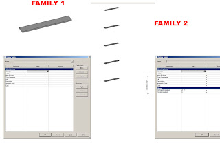
Okay, ill go through the steps of what i did, and you can try it unless someone else has an example for you to reverse engineer. Sorry about that, but my home computer is demo version, it wont save.In IMAGE 1:

1. I made Family 1, just the one piece sweep.


2. I made Family 2, and loaded family 1 in to it. Family 1 is then arrayed, and i put in aparameter for COUNT and DISTANCE. I then assigned the param. COUNT to the label of the array. I dimension the First blade to the second, and assign the label DISTANCE to that dimension. (i went bottom to bottom...)


3. I loaded both families in to Family 3, and placed them both, one on top of the other. The parameters are then set as follows, as shown:


F1V: (Yes/No instance) This will control Family 1 visibility. For the formula, input COUNT = 1. Go to Family 1 that you placed, and go to its properties. Click the gray area at the end of the Visible field, and tie it to F1V.

F2V: (Yes/No instance) This will control Family 2 visibility. For the formula, input COUNT > 1. Go to Family 2 that you placed, and go to its properties. Click the gray area at the end of the Visible field, and tie it to F2V.


Now, make a parameter DISTANCE (length) and ARRAYCOUNT (integer). Go to the Properties of Family 2, and click the gray box at the end of the COUNT field, and tie it to ARRAYCOUNT. Also tie DISTANCE in Family 2 to DISTANCE in Family 3.


Make the Formula for ARRAYCOUNT the following: if (Count>1, Count, 2)What that is doing, is saying if the Value input (for COUNT) is greater than 1, use the value input. if its not greater than 1, use the value of 2, so the family doesnt collapse on itself. This wont matter, because the visibility parameter F2V will make Family 2 not present anyway.

**Peek at image 3. It demonstrates how the if statement, and the visibility parameters will behave. If the value is 1 (for COUNT), the if statement will save the arrays geometry by defaulting ARRAYCOUNT to 2. It will not display Family 2 in the project, so this is irrelevant.

When COUNT is greater than 2, Family 2 shows up with the actual value, and Family 1 is hidden.


4. Load Family 3 in to your project.


Now, in the properties of Family 3 (the actual "FAMILY"), you have a COUNT and a DISTANCE. Through the nested families, the ARRAYCOUNT parameter will make whichever one visible that should be, given the conditions.

If you decided to SHARE the families 1 and 2 (under fmaily catagories and settings, at the bottom) when you loaded them in to 3, (see image IN PROJECT).Both Family 3 AND Family (whichever) will schedule if you made them shared. In my opinion, i wouldnt, because Family 3 is your "actual family" and 1 and 2 are just necessary evils. (Thats more an argument about what youre doing though...)


Also bear in mind, much like Parameters DISTANCE and COUNT, any other parameters you wish to be flexible from the project will have to be nested. For instance, if you want to control the width of the Louvers...Family 1 Parameter WIDTH and Family 2 Parameter WIDTH must both be tied to FAMILY 3 Parameter WIDTH through their properties dialogue, before you load Family 3 in to a project. Because Family 3 is the real family.I hope this makes sense...

Tuesday, April 17, 2007

Autodesk Product Feedback 04-17-2007

I don't know about you guys, but as i stated below... Now that i have the product feedback submittal address, id like to keep up with telling Adsk what i think works great and what i don't. In my opinion, no one has any right to complain about tools lacking, unless they have spoken up.

I'm just putting up a submittal i sent them, about the Imported Objects tab of the VG dialogue. Its a bit ambiguous, in my opinion. We should be organized ourselves, without relying on the tool, but it wouldn't hurt to be a little clearer... :)

"VG dialogue - Imported Objects tab.
The VG dialogue is for Items in a specific view, yet imported items appear in the Imported Objects Tab, even if they have been imported using "This view only" in another view.
This makes isolating imports and keeping track of which consultants drawings are imported on which views difficult, and time consuming.
I may import a Site plan from the civil engineer for a key plan, and then in another view for a Composite Floor Plan. If I've used "This view only" for both views, i get confused often, when going to replace them with updated versions. For the key plan it may not matter, but for the floor plan it does. It is ambiguous figuring out which instances are placed where, if they all show up in every VG dialogue.
Also, when items are not displaying, it is hard to tell if someone has adjusted the VG settings, or if the imported object has been deleted. If someone goes in to the Comp. floor plan i mentioned, and does not see the Site plan, they do not know if the import has even deleted, as it is still in the VG dialogue (from the key plan). So they tend to import another one, bogging down our Revit models unnecessarily.
I don't want this to be a negative submittal, so ill say you guys are doing great! RAC 2008 is wonderful! : )"