I can recall fondly, back in my days working with AutoCAD, i was pretty confident (arrogant) that i had a faster method of drawing than some of the people i worked with. I used "fence trim" while they clicked individual lines, i would array while they would offset and offset, id do this vs theyd do that... And in the end, the end result was always the same. We had all drawn the same door, the same wall, the same window.
So it didnt matter, that i used P-line, and they made 4 lines, then used p-line>join. We both ended up with the same p-line.
Now, in an object oriented environment, I'm left wondering how we bridge the gap with the fact that the "how" might matter now. Objects have information, behavioral tendencies, scheduling criteria.... Objects have implications.
So, when a particular element is in need of modeling, what repercussions lie in wait for a team of three, where one person elects for an out of place family, one person elects for an in place family, and one person elects for a combination of wall sweep and line based component, with some drafted lines in elevation?
I'm discovering that it is imperative that the work be fairly close to uniform, for reasons of efficiency as well as performance. If all three members on my imaginary team are modeling in different fashions, then I've bestowed ANOTHER task on them come revision time: Autopsy. Assuming Wall-Sweep-with-line-based-and-detail-lines guy is on vacation when the design changes, what happens when out-of-place-family guy goes to change it and is dissatisfied with the methodology?
How much time will be spent deconstructing and analyzing (to figure out) and then redoing the same work? How many times are the families getting duplicated, copied, edited, that aren't adding value to the end result?
Ive been thinking about this one for awhile, for a variety of reasons:
"Office standard" families, and families in projects/ or project specific families.
Generic content families, vs families that have been modeled from actual Product Cut Sheets.
"Wall Types and wall types naming conventions"
These are a few areas that I've seen some redundancy tendencies, just in the general work flow. Ive got some ideas on it, hopefully i can get some images and some thoughts up later tonight...
TBC... ...
 This is the first example that comes to find, but (at the risk of being long winded) there is something worth mentioning: There are plenty of ways of achieving the goal. While i contend here and forward that there SHOULD be a uniform way (for a teams benefit), I'm not saying my way is best. Ive conferred with a lot of great modelers, and a lot disagree with how and what I've done. But, for this discussion, these examples will suit fine.
Its a simple building, with some Lights, some EIFS reveals, some Quoins, and some Columns. How do we model it though? Here are the issues i see redundancy in:

The reveals: I tend to make them as a Wall Hosted family, for a few reasons. Maybe they're all horizontal at first, and then are wall sweeps. The client changes spacing, and we adjust. Again. Another adjust. Then he turns them in about a radius, as pictured. Now i have to make a family anyway. Its a toughie, but for the situations like this facade, where there is a Canopy, a raised Band, and the reveals, i try to make them all as one family, for ease of editing. I know a lot of people hate hosted families, but i love them, and use them everywhere. What ill do though, is nest a non hosted family, IN the hosted family. Ive found it makes constraining easier, and gives me a safety net if (for whatever reason) i need a non hosted variant later.
The methodology here, is what i think becomes an issue. Before i showed my colleagues on my team how i made the Reveals, there was an uncertainty when they had to be edited. Surely, someone else found a way: Making the entire wall (solids and voids) as in-place elements. Now, they wouldn't schedule as walls, and they weren't hatched in section. But therein lies the issue: given the opportunity, 5 people may find 5 solutions. How do we combat this? I don't suggest i have an answer, but rather... I'm aspiring to find one...
OBJECTS...
Well, were Object Based, right? Is that ALWAYS a good thing? One issue I've been struggling with, is certifying the integrity of such objects, as they pertain to our Model. 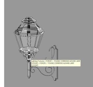 Certainly, with items like Wall lamps, the measurements of the geometry may not be pressing, save for a mounting height. In this case, the client wanted to see them in a rendering. that's neither here nor there. BUT, its another reason i love Nesting families. From the manufacturer, the lamp has several mounting possibilities... Wall mounted, floor mounted... I like the nesting, because i can get a count of how many I've used.
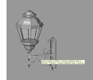
 Certainly, with items like Wall lamps, the measurements of the geometry may not be pressing, save for a mounting height. In this case, the client wanted to see them in a rendering. that's neither here nor there. BUT, its another reason i love Nesting families. From the manufacturer, the lamp has several mounting possibilities... Wall mounted, floor mounted... I like the nesting, because i can get a count of how many I've used.
Here's another one pertaining to this. Have any of you run in to this as well? The columns in the first image... They are GFRC column enclosures spec'd out from a cut sheet. We have them in various sizes, but when i made them originally (my fault), i simply called them "GFRC -24inch" for the family name. So no one had any idea if it was a generic placeholder (for schematic design), or if it was an actual Spec'd piece from a specific manufacturer. later in the project, someone else needed a 24" GFRC in a different model (spinoff project on same campus) and they went to remodel it from the cutsheet... Because they weren't sure that mine was off the cutsheet to begin with.
While it seems like a communication nightmare, i suspect this happens a good bit on large projects with large teams, and large numbers of families. Do any of you use a naming convention to keep track of such a thing? I'm proposing one currently, for our use. I haven't got the nomenclature firmed up yet, but something like this:
GEN - DORIC COLUMN - 24INCH DIA, 16FT
SPC - GLASSWARE COL - MDL 24-16 - WHT
CON- BLDG D - EIFS REVEAL - NW FACADE
To signify: GEN = Generic Content, Schematic Design, No integrity in actual tolerances.
SPC = Manufacturer and model selected, item modeled for Docs (dimensions verified)
CON = Modeled elements that aren't items (like EIFS reveals made in to families...)
Its a toughie. Especially considering the the amount of "I" in your BIM, you may never need an SPC level family. But, when Project Managers come to ask if we can verify that Steel sizes fit in the GFRC's, I'm of the opinion it should be in there.
So i wonder, if the methods to the madness need to all be laid out on the conference room table before the mice hit the pads. It makes for interesting coffee maker conversation with 6 people modeling, that's for sure? Thoughts? Fill me in, i KNOW some of you run in to it too... :)
4 comments:
Hey Aaron, nice blog! Some of my favorites have died down in their content and it's great to see a new one that's posting some involved discussions in great depth.
I think that some guidelines need to be drafted and explained to teams. Of course, someone in the team needs to know how to build families, which in itself is another big hurdle. I guess the key question to be asked is....will these families ever be used again? I'd say, why not? I'd want to re-use them if they're built right. So the guildines/specs are the first weapon in helping to "build them right". The second important thing is cataloguing. How are you going to find these families? There needs to be some system in-place where these families become part of the office library in some searchable way. Otherwise you're just generating data and not information.
I don't have an answer either :) We're about to embark on this journey too. In our case I think we can get by with minimal family building due to our similar project types, but there's no doubt we'll need to establish some ground rules. We're thinking of splitting families in two categories: those that we use firmwide from project to project (plumbing fixtures, toilet stall assemblies, walkway covers, etc) and others that are project-specific. We think that the former are the ones that we should have tight control over and are used to pull together specs, are scheduled, etc. The second category can be a bit more loose, mainly intended to model unique aspects of the building and can be in-place or rfa families. Of course this is just a first step and we might make changes to this philosophy in the future.
I look forward to this continued discussion!
I agree with you, on the needing Office Standard vs Project Specific.
BUT, what happens when someone wants to verify a dimensional clearance around something that is a family? What has the family been modeled to? A loose representation? A specified Cut Sheet?
That is where we run in to trouble. I modeled a light fixture off of a cut sheet, and its in 6 jobs here currently. Someone on a different job wasnt aware the specific fixture had been modeled, as we have no dialogue in place to communicate such things. As such, when they got the cut sheet, they started remodeling.
Hypothetically, even if they knew my family was there, how does one verify that the family is held to a certain standard that can be trusted for such things?
That is why i feel there needs to be GEN content and SPC content, or some other delination in the library.
For instance, the "desk" in the Imp Lib... I certainly cant clearance a room based on it, i haev no idea who manufactures it, LOL...
Aaron, Great discussion even though it's an oldy! I love some of the images you have shown of your model. I know you mentioned that the lines on the face of the wall are wall hosted reveals but those can only be horizontal. How did you come up with the angled reveals. My only guess would be to start with an in place family (solid extrusion). Thanks again!
JB
Justin-
Thanks for the kind words! Just this week i have finally gotten involved in some new projects and hope to be writing much more in the weeks to come!
If you reread the original post, i said they were Wall Hosted Reveals... But what i meant is that theyre built as Wall Hosted Generic Models, that have Void sweeps in them.
I dont like in place families, for a number of reasons. Lack of data, lack of repeatability, and the way they form bizarre constraints and relationships with items around them.
So i go in to a wall hosted generic model, place reference planes to illustrate the extents of the walls, and i use void sweeps. Its problematic that you cannot dimension to the edges of the void sweeps, but with reference lines/planes you can dimension their centerlines in the project.
If you dig through the posts labeled "pics of model and project" you can see the reason i REALLY love using an out of place family. I can repeat these elements down entire corridors, like i did in the Food Court of that model. :)
Post a Comment